Today we all have heard of the theory of relativity, conspiracy theory, the Big Bang theory, etc.
A theory that we have been teaching for over 40 years at Dake is the basic theory of arbor presses. Now, this theory might not be as earth shaking as the theory of relativity, but it does make getting things done a whole lot easier.
Single Leverage Presses
The first thing to remember about arbor presses is that fundamentally, they are a mechanism for converting a small force into a much larger force due to the mechanical advantages obtained by levers and gears.
The principle of the arbor press can be more easily understood by describing the functions of the component parts. The main parts consist of frame, rack, pinion, and handle which are described as follows:
- Handle - produces the motion of the spindle and acts as the long lever in the leverage ratio.
- Pinion or spindle – is a gear which produces the motion of the rack and acts as the short lever in the leverage ratio.
- Rack or ram – is a gear with infinite radius. When used with the pinion it changes rotary motion to a straight-line motion
- Frame – the function of the frame is to support the work piece and act as the support for the spindle and a guide for the ram.
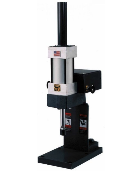
An example of the single leverage arbor press is shown in figure 1. The leverage is the ratio of the distance from the end of the handle to the center of the spindle divided by the pitch radius of the spindle pinion, or: 16"/1/2” = 32:1

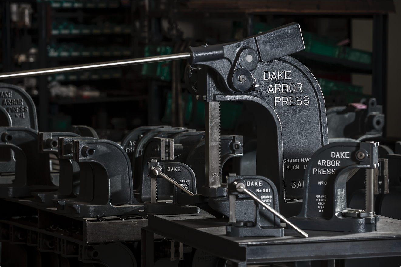
An important thing to note: the Dake 1-1/2, 1-1/2B, 1-1/2C, 1-3/4, 3A, and 4M presses, even though they have lever weights and ratchets, they are still single leverage presses.
The lever weight counterbalances the handle. The ratchet allows the handle to be used in the most convenient position for operator comfort and safety.
The leverage ratio is still equal to the distance from the end of the handle to the center of the spindle divided by the pitch radius of the spindle.
Compound Leverage Presses
The component parts for compound leverage, in addition to those required for single leverage, are the compound, short sliding pin, long sliding pin, pawl, and lever weight defined as follows:
- Compound – is the part which acts as the support for the pawl and the leverweight. It also serves as a lever when either pin is engaged and avoids the use of handles which would be out of proportion to the size of the press.
- Short sliding pin - located in the compound locks the leverweight and compound together when using simple leverage.
- Long sliding pin - located in the frame acts as the pivot for the leverweight when using compound leverage.
- Pawl – is used as a lock between compound and spindle to allow using the handle in the most convenient position.
- Leverweight – is counterbalance for the handle and provides the leverage to operate compound.
These presses can be used either as single leverage presses (for faster pressing speed) or as compound leverage presses (for exerting larger pressing forces).
The compound device multiplies the leverage as follows: With the long sliding pin engaged in the lever weight, a force to the end of the handle is multiplied and added to the compound at the lever weight pin.
The ratio by which the force is multiplied is the distance from the end of the handle to the center line of the long sliding pin divided by the distance between the long sliding pin and lever weight pin.
The compound then multiplies the force applied to it and by means of the pawl transfers it to the spindle and then to the ram.
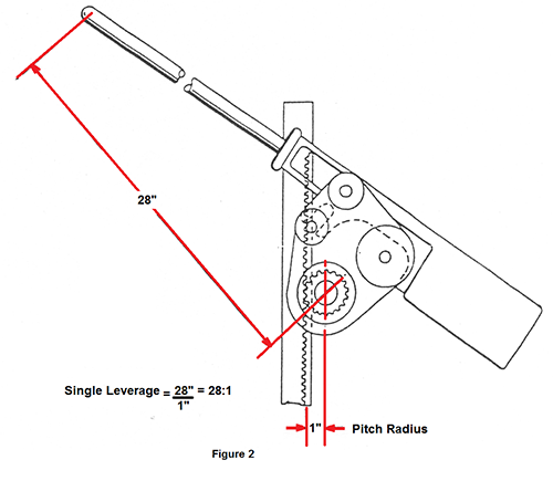
The action of the compound is shown in Fig.2 and Fig. 3. In Fig. 2 the short sliding pin is engaged in the lever weight making the lever weight and compound act as a single unit.

In figure 3 the short sliding pin is withdrawn and the long sliding pin is engaged with the slot in the lever weight.